- 您现在的位置:买卖IC网 > Sheet目录478 > MMA5248WR2 (Freescale Semiconductor)IC ACCELER 480G X-AXIS 16QFN
4.5.4
Daisy Chain Mode
The device can be programmed to operate in Daisy Chain Mode by setting the TRANS_MD[1:0] bits to “Daisy Chain Mode”.
Daisy Chain Mode can be programmed to operate in either “Simultaneous Sampling Mode”, or “Synchronous Sampling Mode”
by setting the LATENCY bit to the desired operating mode. In Simultaneous Sampling Mode, the most recent interpolated accel-
eration data sample is latched at t TRIG (rising edge of Sync Pulse). In Synchronous Sampling Mode, the most recent interpolated
acceleration data sample is latched at the time programmed in TIMESLOTA[9:0], relative to t TRIG (rising edge of Sync Pulse).
When programmed to operate in Daisy Chain Mode, the procedure below is followed:
? On powerup, the device proceeds through normal PSI5 initialization as specified in Section 4.4 using a pre-
defined time slot t TIMESLOT_DCP .
? Upon successful completion of Initialization Phase 3, including the 2 “Sensor Ready” or Sensor Defect”
messages, responses to sync. pulses are terminated and the device waits for a PSI5 “Set Address” command
defined in Table 14 and Table 15 .
– The Daisy Chain Programming command and response formats are defined in Section 5.4 .
– Valid Daisy Chain Addresses are defined in Table 16 .
– The response to the PSI5 Set Address command uses the pre-defined time slot t TIMESLOT_DCP .
? After receiving a valid address and completing the response, sync. pulses are blanked for t DC_BLANKING . Once
the blanking time expires, the device does not respond to any sync. pulses until a “Run Mode” command is
received, as defined in Table 14 and Table 15 .
? When the “Run Mode” command is received, the device responds to this command using the programmed daisy
chain time slot. All commands are then ignored, and sync pulses are responded to with acceleration data using
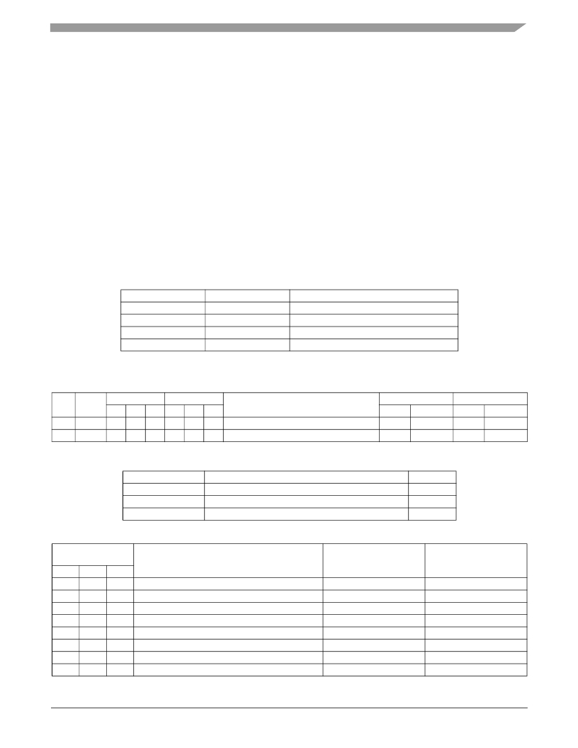
the following response format, regardless of the state of the relevant bits in the Device Configuration Registers:
Parameter
Time Slot
Data Size
Error Checking
Baud Rate
Reference
Section 3.1.4.3
Section 3.1.3.5
Section 3.1.3.7
Section 3.1.3.8
Value
Default time slot specified in Table 16
10-bit data
Even Parity
Low Baud Rate: 125 kBaud
? During initialization and Run Mode, the Sync pulse pulldown is enabled as specified in Section 3.1.3.3 .
Table 14. Daisy Chain Programming Commands and Responses
#
CMD
Type
A2
SAdr
A1
A0
F2
FC
F1
F0
Command
Response (OK)
RC RD1
Response (Error)
RC RD1
D0
D1
Short
Short
0
1
0
1
0
1
A2
0
A1
0
A0
0
Set Sensor Address (Daisy Chain)
Broadcast Message - “Run Mode”
OK
OK
SAdr
0x000
Error
Error
ErrN
ErrN
Table 15. Daisy Chain Programming Response Code Definitions
Response Code
RC = OK
RC = Error
SAdr
Table 16. Valid Daisy Chain Addresses
Sensor Address
Definition
Command Message Received Properly
Error during transmission of Command Message
Programmed Sensor Address, prepended with 0s
Value
0x1E1
0x1E2
Varies
A2
(SAdr)
A1
A0
Description
Bus Switch Control
Default Time Slot
0
0
0
0
1
1
1
1
0
0
1
1
0
0
1
1
0
1
0
1
0
1
0
1
Address of un-programmed sensor
Sensor Address 1
Sensor Address 2
Sensor Address 3
Sensor Address 4
Sensor Address 5
Sensor Address 6
Global Address for Broadcast Message to all Sensors
N/A
CLOSED
CLOSED
CLOSED
OPEN
OPEN
OPEN
N/A
N/A
t TIMESLOT_DC1
t TIMESLOT_DC2
t TIMESLOT_DC3
t TIMESLOT_DC1
t TIMESLOT_DC2
t TIMESLOT_DC3
N/A
MMA52xxKW
Sensors
Freescale Semiconductor, Inc.
47
发布紧急采购,3分钟左右您将得到回复。
相关PDF资料
MMA6331LT
SENSORS ACCELEROMETER 14LGA
MMA6341LT
IC ACCELER 3G/8G XY-AXIS 14LGA
MMA6361LT
IC ACCELER 1.5G XY-AXIS 14LGA
MMA6527KW
IC ACCELEROMETER XY AXIS 16QFN
MMA6556KW
IC ACCELEROMETER X AXIS 16QFN
MMA6826AKW
IC ACCELEROMETER XY AXIS 16QFN
MMA6854KW
IC ACCELEROMETER X AXIS 16QFN
MMA7331LR2
ACCELEROMETER 4G XYZ ENH 14-LGA
相关代理商/技术参数
MMA52XXAKW
制造商:FREESCALE 制造商全称:Freescale Semiconductor, Inc 功能描述:Xtrinsic MMA52xxAKW PSI5 Inertial Sensor
MMA52XXKW
制造商:FREESCALE 制造商全称:Freescale Semiconductor, Inc 功能描述:PSI5 Inertial Sensor
MMA52XXWR2
制造商:FREESCALE 制造商全称:Freescale Semiconductor, Inc 功能描述:PSI5 Inertial Sensor
MMA621010AEG
功能描述:加速计 - 板上安装 100/100G XY ANALOG RoHS:否 制造商:Murata 传感轴:Double 加速:12 g 灵敏度: 封装 / 箱体: 输出类型:Analog 数字输出 - 位数:11 bit 电源电压-最大:5.25 V 电源电压-最小:4.75 V 电源电流:4 mA 最大工作温度:+ 125 C 最小工作温度:- 40 C
MMA621010AEGR2
功能描述:加速计 - 板上安装 100/100G XY ANALOG RoHS:否 制造商:Murata 传感轴:Double 加速:12 g 灵敏度: 封装 / 箱体: 输出类型:Analog 数字输出 - 位数:11 bit 电源电压-最大:5.25 V 电源电压-最小:4.75 V 电源电流:4 mA 最大工作温度:+ 125 C 最小工作温度:- 40 C
MMA621010AKEG
功能描述:加速计 - 板上安装 100/100G XY ANALOG RoHS:否 制造商:Murata 传感轴:Double 加速:12 g 灵敏度: 封装 / 箱体: 输出类型:Analog 数字输出 - 位数:11 bit 电源电压-最大:5.25 V 电源电压-最小:4.75 V 电源电流:4 mA 最大工作温度:+ 125 C 最小工作温度:- 40 C
MMA621010AKEGR2
功能描述:加速计 - 板上安装 100/100G XY ANALOG RoHS:否 制造商:Murata 传感轴:Double 加速:12 g 灵敏度: 封装 / 箱体: 输出类型:Analog 数字输出 - 位数:11 bit 电源电压-最大:5.25 V 电源电压-最小:4.75 V 电源电流:4 mA 最大工作温度:+ 125 C 最小工作温度:- 40 C
MMA621010EG
功能描述:加速计 - 板上安装 100 /100 XY DIGITAL RoHS:否 制造商:Murata 传感轴:Double 加速:12 g 灵敏度: 封装 / 箱体: 输出类型:Analog 数字输出 - 位数:11 bit 电源电压-最大:5.25 V 电源电压-最小:4.75 V 电源电流:4 mA 最大工作温度:+ 125 C 最小工作温度:- 40 C
